Power Analysis
A power meter is used to measure electrical power, the product of voltage and current. In order to record both parameters, those devices are equipped with analogue and digital measurement techniques. Often they vary in the count of possible recordable channels.
More specialized power meters, which have extremely high accuracy and a large number of additional analysis functions (e.g. FFT), are also called power analyzers. These are used to determine the efficiency of electrical drive components such as electric motors or power inverters.
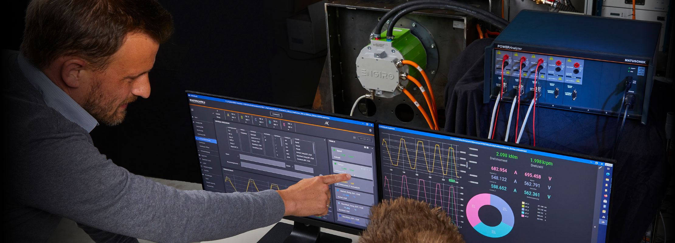
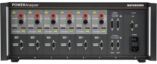
The LK601 multi-channel power analyzer was specially designed for use on drive test benches. This significantly simplifies development, analysis and end-of-line testing. You need more information? Then follow this link.
Accuracy specifications of power analyzer are highly complex and usually comprise several pages of the product documentation. The accuracy depends on the frequency, the power factor and the modulation of the ranges. It is common to state the accuracy of the power at a value of 50Hz.
An accuracy of <0.05% is one of the values that good power analyzers achieve there. However, this is only one of many parameters that describe the accuracy of a device. There is also no standardization. Which information is given depends on the manufacturer. They indicate their own boundary conditions.
This is why the reputation of a brand is particularly important, as customers have to rely on the manufacturer's information. A high level of accuracy is important because modifications to the device under test are often only marginally noticeable. Though, it still can have an enormous effect on the overall efficiency.
In addition, technical modifications to the product are only made step by step. The influence on the overall result can/must be precisely documented and controlled. A clean and comprehensible documentation is essential for later processing. Future development can then benefit from previous work.
Development of electric drive systems: overall efficiency determination of e-machine, inverter, cooling system, gearbox
Development of electric machines: efficiency map determination, endurance test, stress tests
Development of power inverters for electric motors: efficiency map determination, endurance test, stress tests
Development of switching power supplies: efficiency, no-load power, harmonic analysis
EOL-testing of e-drive components: If there are deviations from the standard values, errors in production can be detected. Improve quality monitoring!
Certification processes: Many standards require information about electrical performance, energy consumption or the efficiency of products and components.
Verification of FEM simulations
The most important characteristic of a power analyzer is the acquisition of current and voltage. The speed at which the data is acquired and processed depends on the dynamics of the application. For this it is particularly important that power analyzers record this extremely accurate and replicable even at low power factors.
The system must be able to perceive the smallest changes to the device under test (DUT). An increase in efficiency of only 0.5% can, for example, lead to enormous competitive advantages in the development of electric motors. The system should also be error-resistant.
If the operation is too complex, incorrect settings may occur which falsify the result of the measurement. The operator effect and user experience is often underestimated. As a consequence incorrect measurements may occur.
Concluding, a power analyzer should have the following characteristics:
The power measurement in a 3-phase system (3P) can be done in different ways depending on the number of wires (W). Depending on the configuration, the measured values must be evaluated differently for the correct determination of the power or do not provide any direct information about the variables prevailing in the system.
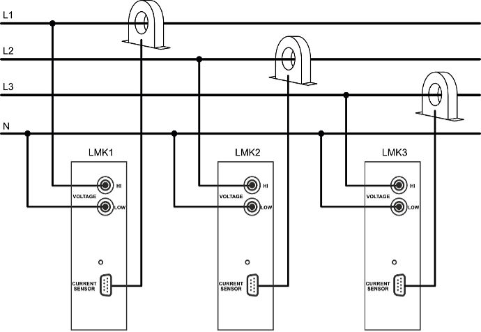
In addition to the 3 phases L1, L2, L3, the neutral conductor N is also available as a fourth wire for power measurement in the 3P4W variant. The three required power measurement channels LMK1 to LMK3 are connected as shown in the figure. A power measurement channel measures the electrical power of the respective phase. The neutral conductor is used as a common voltage reference. The total power is the sum of the measured individual powers of the respective phases.
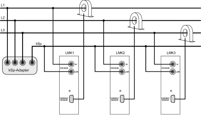
The neutral conductor is often not present. For example, many electric drive applications like electric machines do not provide the star point for external access. By using an artificial neutral point, this missing reference center is generated externally. Used as a reference point, the power of each phase and the total power can be determined as in the 3P4W arrangement with three power measurement channels. The total power is the sum of the measured individual powers. The figure below shows the corresponding connection diagram.
If the neutral point is not available, the total power can be determined using the Aron circuit without an artificial neutral point. With this method of power measurement, two power measurement channels are sufficient. If the sum of the instantaneous values of the phase currents is zero, one of the phases can be considered as a common return. The figure shows the corresponding measurement setup.
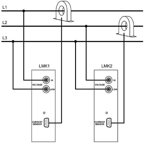
Two phase currents are recorded by the two current sensors. The two voltage inputs of the measuring cards measure phase-to-phase voltages. As a result, the services displayed do not correspond to the individual services of the respective strands. However, the total power can be determined by adding these two powers. This only applies under the condition that the sum of all instantaneous phase currents is zero. When operating electrical machines on frequency converters, leakage currents can occur due to capacitive coupling to ground, which falsify the measurement result. In this case, the sum of the phase currents is not equal to zero. Therefore, the Aron circuit is not recommended for a measurement on a converter.
With the 3V3A configuration, 3 power measurement channels are used. However, since there is no neutral conductor or neutral point available here either, a phase is used as a reference. The figure shows the corresponding connection diagram.
The first power measurement channel LMK1 measures the current in phase L1 and the voltage between phases L1 and L3. LMK2 measures the current IL2 and the voltage between L2 and L3. Phase 3 represents the reference point for the first and the second power measurement channel. The third measuring channel LMK3 measures the phase current IL3 and the line-to-line voltage UL1-L2.
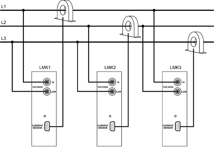
In the configuration shown above, the total power is obtained from the sum of the two powers LMK1 and LMK2. It is important to note that none of the individual values (LMK1 to LMK3) corresponds to the correct individual power of the respective phases! Even if two power measurement channels are sufficient for calculating the total power, it is still advisable to use the 3V3A method. By sensing all three phase currents and voltages, statements can be made about symmetries and any leakage currents that may occur.
When measuring power, a distinction is made between electrical and mechanical power.
The values
are considered to be electrical power values.
An input for torque and speed is required for the calculation of mechanical power. The actual sensing of
these values takes place within a torque measuring shaft.
Current and voltage are measured directly. After the analog quantification, the signals are digitized. These values are then multiplied and averaged in real time. This is how the real power is calculated. The digital availability of the measured values also enables to derive other variables. Furthermore these data also offer the option of filtering.
The basic measuring method does not depend on AC or DC. With AC, the entire signal period must be taken into account. With a sine, for example, the power also looks like a sine. However, it is essential to average the entire period, otherwise there will be beats (flickering measured values). That makes an exact reading impossible. With DC signals the power can be read off at any time.
Reactive power: Reactive power does not affect the energy balance of the system. But it still has to be made available. It is a pendulum power that does not affect the energy balance due to the recurring energy flow. It is not entirely necessary to keep the reactive power low, but this is desirable. The greater the reactive power, the stronger the electrical components have to be designed. Resulting in more volume, more weight and more costs.
Real power: Unlike reactive power, real power actually has an effect on the energy balance. It is the electrical power that "actually" matters. It is an effective gain or loss in energy.
Apparent power: Apparent power describes the sum of active and reactive power. The apparent power does not allow any information about whether there is actually a lot or little "real" power. For example, a high apparent power with high reactive power can have a lower real power than a low apparent power with low reactive power.
In the segment of power meters, a distinction must be made according to the application use. For end user applications, "simple" power meters, also called watt meters, are more interesting. These have a limited range of functions and are also less precise than highly professional devices in terms of their accuracy. The areas of application for watt meters are particularly in the home for tracking down "energy guzzlers".
Power analyzers differ from watt meters in that they are much more accurate. They work with a larger range of functions, but are also a lot more complicated. They are used in professional environments for R&D activities and EOL testing.

Electromobility
rethought.
Matuschek Meßtechnik GmbH
Werner-Heisenberg-Str. 14
52477 Alsdorf
Germany